A handful of tugs have reported problems associated with the muffler. Today I got to see a failure firsthand when Pet Tug #60's muffler split apart while the tug was underway. The split occurred along the fiberglassed joint between the unit's top and bottom halves. According to Lou Steplock, there was a loud bang and oily water went everywhere in the engine room. After the muffler was removed only a little bit of fiberglass held its two halves together--resembling something like the hinge on a clam shell. Not much effort was required to get the halves apart. Once apart several things became clearer. The fiberglass tubes, which the exhaust hoses attach to, we're formed around what appears to be PVC. As the picture shows, Pet Tugs' PVC was deforming and small pieces of burnt PVC were found in freely floating inside the muffler.
On Pet Tug #60, where the normal sink and stove positions are swapped, i.e. stove inboard and sink outboard, the galley width is 1" and the Tommy door is 1" deeper.

Monday, August 27, 2012

Wednesday, July 18, 2012
What I Learned from Ed McChain
What I learned from Ed McChain, Thistle #47
By Dave Howell, Nellie D. #63
1. By rotating the Dutch door's exterior escutcheon 120 degrees, the door handle can't vibrate itself open--and thus the door hooks aren't required. This not only makes the doors safer but easier to use too.
2. Getting aboard an LNVT from the water is problematic. Using the engine room's ladder on the bulwark's exising pintles is not really satisfactory because (1) the ladder doesn't go far enough into the water and (2) it's hard to climb the ladder's negative slope. Ed bought a marine ladder and then made a PVC adapter to mate the ladder to the existing Pintles.
3. To cool the engine room Ed installed a ducted fan near the ceiling and then vented it by drilling a new hole in the cabin side just aft of the existing portside engine room grille. He could have used the existing engine room vent but feared he'd diminish the little natural airflow that already exists. Using the ducted fan reduces the engine room's ambient temperature by 20F.
4. If you want to know what dinghy handling systems really work, talk to a pet owner that likes to anchor out. Ed takes his two pups ashore regularly using his 8' sailing dinghy and 2hp (?) engine. I watched him singlehandedly stow the dink, with the engine attached, on the O2 deck, in a total of two minutes, using an electrically powered davit. The davit is mounted to the port, aft corner of the salon. it's tall enough to lift the dink over the O2 deck's lifelines. Ed estimates the dink weighs around 200 pounds. The dink sits on chocks just aft of the companionway hatch. There wasn't any noticeable heeling of Thistle as the dink was lifted.
By Dave Howell, Nellie D. #63
1. By rotating the Dutch door's exterior escutcheon 120 degrees, the door handle can't vibrate itself open--and thus the door hooks aren't required. This not only makes the doors safer but easier to use too.
2. Getting aboard an LNVT from the water is problematic. Using the engine room's ladder on the bulwark's exising pintles is not really satisfactory because (1) the ladder doesn't go far enough into the water and (2) it's hard to climb the ladder's negative slope. Ed bought a marine ladder and then made a PVC adapter to mate the ladder to the existing Pintles.
3. To cool the engine room Ed installed a ducted fan near the ceiling and then vented it by drilling a new hole in the cabin side just aft of the existing portside engine room grille. He could have used the existing engine room vent but feared he'd diminish the little natural airflow that already exists. Using the ducted fan reduces the engine room's ambient temperature by 20F.
4. If you want to know what dinghy handling systems really work, talk to a pet owner that likes to anchor out. Ed takes his two pups ashore regularly using his 8' sailing dinghy and 2hp (?) engine. I watched him singlehandedly stow the dink, with the engine attached, on the O2 deck, in a total of two minutes, using an electrically powered davit. The davit is mounted to the port, aft corner of the salon. it's tall enough to lift the dink over the O2 deck's lifelines. Ed estimates the dink weighs around 200 pounds. The dink sits on chocks just aft of the companionway hatch. There wasn't any noticeable heeling of Thistle as the dink was lifted.
Tuesday, July 17, 2012
Cummins 4BT-3.9M 150hp Fuel Consumption
Data came from a newly installed Flowscan on Hjortie #33. As a sanity check Hjortie's data is compared to Nellie D's #63 data which was collected last year.
| RPM | Hull 33 | Hull 63 |
|---|---|---|
| 1200 | .7 | .9 |
| 1400 | 1.1 | 1.2 |
| 1600 | 1.4 | 1.6 |
| 1700 | 1.7 | 1.7 |
| 1750 | 1.8 | |
| 1800 | 2.0 | 1.9 |
| 1950 | 2.4 | |
| 2000 | 2.5 | 2.8 |
| 2200 | 4.0 | 3.6 |
Monday, February 27, 2012
List of Known LNVT Issues
The following is a partial list of issues which LNVTs may face sometime during their lifetimes:
- Replace BMW diesel ($18,000)
- Fuel tank replacement ($12,000 or $5,000 DIY)
- Window channel replacement ($150 DIY)
- Window frame rebed ($50 DIY)
- Cummins exhaust elbow replacement ($1,800 or $1,600 DIY)
- Turbocharger rebuild ($1,600)
- Replace 3" wet exhaust hose ($300 DIY)
- Rebuild diesel injector pump ($400 DIY)
- Replace stainless water tank lid parts with plastic ($100 DIY)
- Bulwark gel coat crack repair
It would be good to expand this list to all known issues.
Thursday, August 18, 2011
Teak Deck and Fuel/Water Filler
According to John Isaksen, Neptune (35), and confirmed by Tommie Chen, the teak decks are held down with a black adhesive. It's the same polysulfide-like material used in the deck seams and window jams. The decks' teak was originally 1/2" thick. This was determined by removing the fuel-deck-fill-plate, which protected the underlying wood from erosion, and measuring its thickness. The deck's overall thickness at the filler port is 1-3/4". The fiberglass appears to be 1" thick. There's a 1/4" of plywood under that. The filler port appears to have had a 3" extension spout welded to it.
Tuesday, July 12, 2011
What Supports the Teak and Holly Sole?
So what does support the 13/16" thick floor boards? In a nutshell, floor joists. The joists are 2" thick by 1-3/4" wide. There's a stringer, fiberglassed into the hull, upon which the joists, running athwart, rest upon. The joists are fixed to the stringer by fiberglass. According to Tommy Chen, inside the stringer is a wood called 'Yako' which is very much like iron wood.
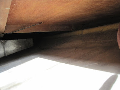
Looking forward and outboard on the starboard side. The stainless water tank is forward.

Looking outboard at the floor support structure. Starting at the bottom are: (1) turn of the bilge for the fiberglass hull; (2) a stringer fiberglassed to the hull; (3) a floor joist that has been fiberglassed to both the stringer and the hull; and (4) a fixed portion of the floor.
Saturday, May 7, 2011
Wet Muffler Failures and the Injection Elbow
Some LNVTs with over 4000 hours on their Cummins engines have reported wet muffler failures. Autopsies of these mufflers turned up melted components. After the obvious causes were eliminated, broken impeller, blocked thru-hull, etc, it was thought that the melting was due to poor muffler material selection by the manufacturer. However, the cause may very well lie in the exhaust's wet injection elbow. Over time carbon build-up in the elbow reduces the raw water's cooling efficiency. Cooling efficiency is important because depending on RPM the exhaust's temperature is between 350 and 800F. The muffler, which is only about 3' away from the elbow and made of FRP, can withstand temperatures to around 250F. Thus an engine running at high RPM that has carbon build-up in the injection elbow could conceivably go over-temp in the muffler. A recent inspection of Nellie D.'s (63) 4500 hour elbow showed significant carbon build-up. When the carbon was removed from the elbow, extensive crevice corrosion was found. So much so that the elbow had to be replaced. It's probable that the crevice corrosion was exacerbated by the carbon because it allowed a very caustic micro environment to form.
I now have many good reasons to bi-annually inspect for and remove carbon build-up on the inside of the elbow, not the least of which is its $1600 replacement cost.
For some good background information I recommend the following articles:
Saturday, January 8, 2011
Gel Coat Rub Rail Cracking Revisited (see also 20 December 2010)
Gel coat should be applied anywhere from .012" to .026" thick. A sample of gel coat just below Nellie's waterline measured .019", well within tolerances. However, as the picture at right shows, the crack's gel coat thickness is three to four times the ideal.

Thursday, December 30, 2010
Fuel tank venting
Several years ago Phil de l'Etoile, Brave Duck #67, discovered his fuel vent lines were clogged with fuel. This week it dawned on me that every LNVT with fuel vents on top of the tank will suffer the same problem. That's because after leaving the tank, the 3/4" vent hose must dip down to get under the floor joist. It's only a matter of time until the dip fills with fuel. Fuel-filled vent lines also explain why there have been so many Forum discussions concerning filler port fuel eruptions during refueling operations.
Phil's solution, which is fix-and-forget, is pictured below. The vent on the port forward tank was relocated to a new location about 2" down the tank's side. This required drilling into the tank and installing a 3/4" fitting. The abandoned fitting on the top of the tank was plugged. Then the two forward tanks were connected together with 3/4" hose. A 'T' was put in the connecting hose and leads to the cabin-sides vent port. Care was taken to make sure the vent hose slopes only upwards from the 'T' to the cabin-sides vent port. Now, any fuel that enters the vent hose will automatically be routed back to the port forward fuel tank. The aft tanks were vented in a similar fashion except the starboard tank had the new fitting installed. To work properly, the tanks with the new taps can be filled no higher than those taps. This results in a reduction of fuel carrying capacity of approximately 30 gallons ( 2" x 2 tanks x 7.5 gal/" = 30 gal).
Another solution, which admittedly isn't fix-and-forget, is to pretty much leave the venting system as-is but install a trap to give the fuel caught in the vent hose someplace to go. From the aft tank the vent hose runs forward and constantly downward until it arrives abeam and about 2" below the forward tanks vent port. Here the forward tanks' vent 'T's in. Another 'T' just forward leads the hose ever-upwards to the cabin-sides' vent port. Attached to the downward facing leg of the second 'T' is a piece of clear 3/4" hose, about 2' long, which is capped on the bitter end. Since the clear trap line is lower than the vent, it will collect any fuel. Only when the trap is full does it need to be drained.

Starboard tank shows vent on top while port tank has vent on side

Here the starboard vent has been relocated to the side of the tank while the port vent is on top.

Phil's solution, which is fix-and-forget, is pictured below. The vent on the port forward tank was relocated to a new location about 2" down the tank's side. This required drilling into the tank and installing a 3/4" fitting. The abandoned fitting on the top of the tank was plugged. Then the two forward tanks were connected together with 3/4" hose. A 'T' was put in the connecting hose and leads to the cabin-sides vent port. Care was taken to make sure the vent hose slopes only upwards from the 'T' to the cabin-sides vent port. Now, any fuel that enters the vent hose will automatically be routed back to the port forward fuel tank. The aft tanks were vented in a similar fashion except the starboard tank had the new fitting installed. To work properly, the tanks with the new taps can be filled no higher than those taps. This results in a reduction of fuel carrying capacity of approximately 30 gallons ( 2" x 2 tanks x 7.5 gal/" = 30 gal).
Another solution, which admittedly isn't fix-and-forget, is to pretty much leave the venting system as-is but install a trap to give the fuel caught in the vent hose someplace to go. From the aft tank the vent hose runs forward and constantly downward until it arrives abeam and about 2" below the forward tanks vent port. Here the forward tanks' vent 'T's in. Another 'T' just forward leads the hose ever-upwards to the cabin-sides' vent port. Attached to the downward facing leg of the second 'T' is a piece of clear 3/4" hose, about 2' long, which is capped on the bitter end. Since the clear trap line is lower than the vent, it will collect any fuel. Only when the trap is full does it need to be drained.
Starboard tank shows vent on top while port tank has vent on side
Here the starboard vent has been relocated to the side of the tank while the port vent is on top.
Tuesday, December 28, 2010
How Loud is it in the Pilothouse?
The following noise level readings were taken while underway using an Ipod Touch 4G running Sound Level(TM)—a free app. I was standing in the middle of the pilothouse, facing forward. The Touch was held upright and was about 5'4" high . Hmm, looks like Nellie has a resonance problem at 800 rpm ;-)
| RPM | Nellie D. (63) | Knock Off (66) |
|---|---|---|
| db | db | |
| 600 | 65 | |
| 800 | 79 | |
| 1000 | 71 | 68 |
| 1200 | 71 | 72 |
| 1400 | 73 | 73 |
| 1600 | 75 | 72 |
| 1750 | 74 | |
| 1800 | 77 | |
| 2000 | 79 | 79 |
| 2200 | 83 | |
| 2400 | 84 |
Saturday, December 25, 2010
The Ceiling Lights—An Easy Fix to an Old Problem

Pretty but not always functional
The ceiling lights are finicky—to put it nicely. Invariably either the red, white, or both lights don't turn on. It's not that the bulbs are burned out either; it's simply a bad connection between the bulb and socket. As the close-up picture of the bulb shows, there's a circular deformation in each of the bulb's contacts. Heating, due to a poor electrical connection, allowed the socket's steel pins to sink into the bulb. To fix the problem the contact between bulb and socket needs to be kept clean and oxidation free. Something easier said than done in a salt water environment. Fortunately the fix is easy; before installing the bulb simply apply marine electronics grease to its contacts. This will keep the environment at bay and help dissipate heat too.
Replace the old bulbs or grind-out the indents

Liberally grease the bulb's contacts before reinstallation

By removing only two screws and loosening the third, the lens easily slides out

Note the heat-caused indents in the bulb's contacts
Monday, December 20, 2010
Gel Coat Rub Rail Cracking
What causes those consistent and persistent LNVT rub rail cracks and how can they be eliminated once and for all? The cracks are consistent in that they almost always appear on the upper (i.e. the skyward) section of the rub rail and are usually nearly vertical. They're persistent in that many owners have repaired the cracks only to have new ones appear. When Nellie D. was repainted last year her many rub rail cracks were ground out, filled and faired. These cracks were only in the gel coat and did not penetrate the underlying fiberglass. So, what's causing these cracks? I had an experience yesterday that got me thinking. But first I must digress.
 |
| An opening in the stern bulwark clearly shows the rubrail's curved indent |
I've preformed some exceptionally ugly landings lately. Yea, it's been 10 months since I've had Nellie out—but still. Anyway, during the last 'crash' I managed to drive Nellie's hull, just below the stateroom's port light , rather abruptly into the corner of the floating dock. Fortunately the dock was well padded and left only a rubbery raspberry on the hull. After counting my blessings, and spending 30 minutes removing the offending blemish, I noticed a big, new rub rail crack (see photo) almost directly above the point of impact. Hard to believe my little bump didn't contribute to this new battle scar. On the other hand, some strong winds in the past few days had pushed us rather forcefully against the floating dock. Either event would cause the hull to flex and I've suspected that movement of the fiberglass substrate is the root cause. Flexing can be caused by many types of dynamic loading: a rough passage; bumping a dock, a piling, or even from a fender; and certainly from the straps during a haul-out. But why does this otherwise normal fiberglass flexing manifest itself as a crack only in the rub rail?
 |
| The new crack … |
So here's the theory, the hull mold was upside down, i.e. keel facing up, when it was sprayed with gel coat. Remember, the hull mold includes not only the rub rail but the bulwark too. Imagine a guy standing inside the hull with a spray-gun trying to put an even, thin layer of gel coat on all the surfaces surrounding him. It's fairly easy to do on the large flat areas of the turn-of-the-bilge, hull sides, and bulwark, but the rub rail, which is the nexus between the hull sides and bulwark, is a narrow, 6", concave indent (see first photo). If the spray was too thick in the indented area, the gel coat would run and pool on the indent's lower back and bottom surfaces. The exact surfaces, in fact, where today's rub rail cracks appear. Thus it's this too thick gel coat that's the problem; unlike the thinner gel coat everywhere else, the too thick gel coat can't handle the nominal deformations of the fiberglass it's attached to. The only practical way to eliminate rub rail cracking then is to get out the sander and remove the too thick gel coat.
See: Getting a Handle on Gel Coat Cracking, by Bob Lacavara
Tuesday, December 7, 2010
Lani Hart's Lord Nelson History
Received an email from Lani Hart in which she documents the Lord Nelson Corporate history. Very interesting.
Saturday, December 4, 2010
Cummins 4BT3.9M Fuel Consumption Measurements
So how much fuel does a 150hp Cummins 4BT-3.9M use? The following data was compiled in calm conditions, aboard Nellie D. #63 on the Caloosahatchee Canal west of Lake Okeechobee, Florida. RPM readings came from the helm's VDO tachometer, ground speed came from a Garmin GPS and fuel flow rates came from a Flowscan.
| RPM | Knots | GPH |
|---|---|---|
| 600 | 3.3 | .2 |
| 700 | 3.5 | .3 |
| 800 | 3.6 | .4 |
| 900 | 4.2 | .5 |
| 1000 | 4.7 | .6 |
| 1200 | 5.5 | .9 |
| 1300 | 5.8 | 1.0 |
| 1400 | 6.1 | 1.2 |
| 1500 | 6.4 | 1.4 |
| 1600 | 6.7 | 1.6 |
| 1700 | 6.8 | 1.7 |
| 1800 | 7.2 | 1.9 |
| 1900 | 7.5 | 2.4 |
| 2000 | 7.7 | 2.8 |
| 2100 | 7.8 | 3.1 |
| 2200 | 8.0 | 3.6 |
| 2300 | 8.3 | 4.3 |
| 2400 | 8.4 | 5.1 |
Thursday, December 2, 2010
Why have a Waterlift Muffler?
One reason to have a waterlift muffler, according to John Mackie, John William #68, is to prevent water, which is aft of the muffler but has yet to be discharged overboard, from backing up into the engine. This could occur in large seas when the bow is down. Interestingly, Knock Off #66, has no muffler at all.
Subscribe to:
Posts (Atom)